



ULTRATUBE – ultrasonic testing unit for small- and medium-diameter electric-welded and seamless pipes
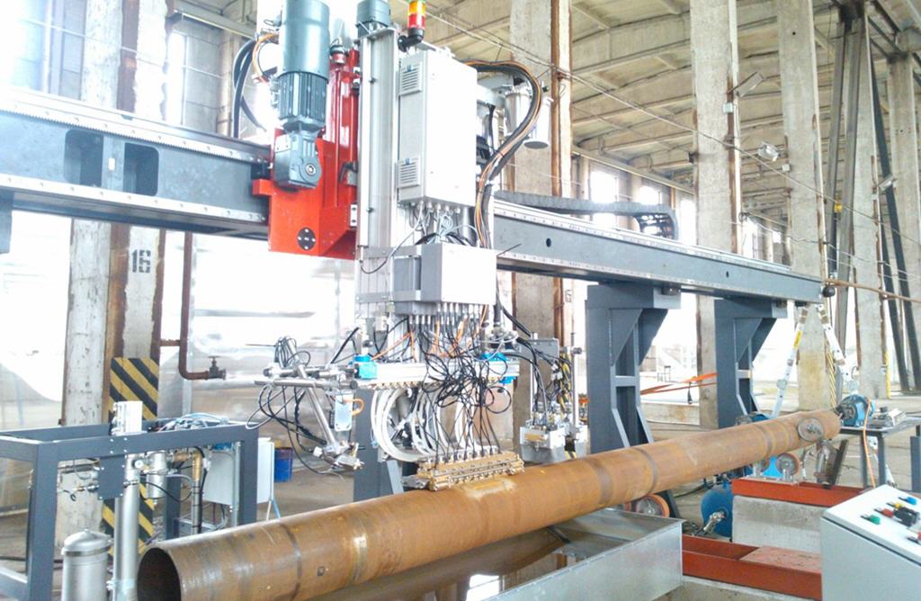
The ULTRATUBE ultrasonic NDT system enables:
- flaw detection and wall thickness measurement of the pipe body;
- detection of longitudinal and transverse defects in the weld seam and the heat-affected zone of the welded joint;
- detection of laminations at the pipe ends.
Ultrasonic testing of electric-welded and seamless pipes is performed to detect and reject products with unacceptable longitudinal and transverse defects, base metal laminations and out-of-tolerance wall thickness. The unit performs automated ultrasonic testing of electric-welded and seamless pipes by means of longitudinal and transverse defect testing subsystems and a wall thickness measurement subsystem.
Ultrasonic testing is carried out using the pulse-echo method. The unit operates the acoustic transducers in pulse-echo (single-probe) mode. The required testing parameters and tolerances are ensured by setting up the equipment on reference standards.
Equipment features
The ULTRATUBE unit comprises:
- mechanical equipment;
- pneumatic equipment;
- electronic-acoustic testing system;
- automatic control system;
- control computer system;
- power supply system.
The mechanical equipment ensures acoustic coupling of the piezoelectric transducers (PETs) or EMATs with the pipe as it moves at a specified speed through the ultrasonic measuring modules.
The electronic-acoustic testing system provides complete continuous scanning of the metal of the moving pipe by means of two measuring modules. The measuring modules of the transverse defect, longitudinal defect and wall thickness measurement subsystems are structurally separate in the unit.
Generation of probing pulses, reception and primary processing of echo signals are performed by the ultrasonic electronics. The ultrasonic testing data obtained are transferred in digital form to the computer system for further software processing.
ULTRATUBE units use methods of continuous ultrasonic inspection of small- and medium-diameter electric-welded and seamless pipes made of low-carbon and low-alloy steels. The system is based on ultrasonic flaw detection methods involving the transmission, reflection and mode conversion of ultrasonic waves in metals.
Continuous scanning of the pipe is performed with piezoelectric transducers (PETs, phased arrays) or electromagnetic acoustic transducers (EMATs); ultrasonic testing can be carried out with conventional piezoelectric transducers as well as with phased arrays.
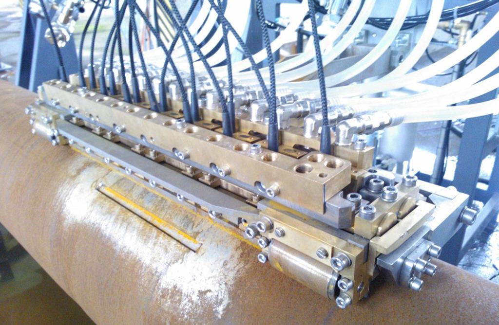
The phased array scans the weld cross-section in real time at various angles. This makes it possible to detect unfavourably oriented critical defects in the weld seam.
The unit implements additional insonification schemes stipulated by special requirements: testing for transverse defects in the heat-affected zone, On-Bead, TOFD.
The design and arrangement of the acoustic transducers place the acoustic focus in the region of the opposite pipe wall in order to obtain the maximum echo signal amplitude.
In each testing cycle step, one of the acoustic transducers generates a bulk longitudinal wave propagating normal to the pipe surface.
The testing cycle for one pipe section may consist of several steps with accumulation of the received signals, which reduces the level of noise and interference that degrade the quality of non-destructive ultrasonic testing.
The cable connections that carry the probing pulse are elements for matching the acoustic path. The parameters of the transmission line, determined mainly by its length and cable type, are of great importance here.
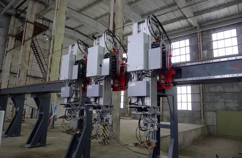
All testing units are mounted on a movable module (platform) that moves them along the rotating pipe while it is scanned.
For each defective pipe, a test report with a defect location map (defectogram) is printed. Defective pipe sections are marked with paint.
Equipment versions
- Gantry type: during testing the pipe rotates on turning rollers while the measuring module moves along the pipe, scanning its entire circumference. Both longitudinal and transverse loading/unloading of the pipe into the testing zone are possible.
- Stationary type: the pipe moves helically (rotating and advancing) through the testing zone. The stationary measuring module scans the entire pipe as it is conveyed through the testing zone.
Control computer system
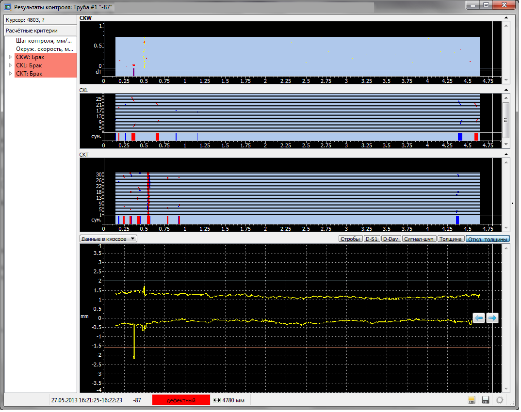
The control computer system provides:
- quality control in accordance with the established rejection rules;
- real-time diagnostics;
- pipe sorting;
- display of information on defective zones, with their representation on the mimic diagram;
- classification of discontinuities as "acceptable" and "unacceptable";
- alarm signalling of unacceptable defects and output of a control signal to activate the defect marker;
- printing, archiving and storage of test reports;
- communication with the higher-level computer (integrated system).
Quality testing system for welded joints and the heat-affected zone
The position of the pipe weld seam is tracked by a non-contact laser scanner and, if necessary, the pipe position on the rollers is corrected automatically.
The testing system for the weld seam and the heat-affected zone consists of several transducers.
The TOFD scheme used for testing the weld seam and the heat-affected zone detects arbitrarily oriented defects in the middle part of the weld seam, including defects with a small opening. This scheme can supplement (or replace) the TANDEM scheme. In addition, TOFD makes it possible to determine the actual size of defects.
Metal thickness and lamination testing system
The channels of the wall thickness measurement subsystem operate in pulse-echo (single-probe) mode. The probing subsystem includes an acoustic transducer, pulser-amplifier units and a decoupling unit.
For wall thickness measurement and lamination detection, the pipe wall is insonified radially.
Internal defect testing system
The system detects longitudinal and transverse defects in the pipe metal. During testing, the pipe is insonified circumferentially to detect longitudinal defects and along the generatrix, in the direction of pipe travel, to detect transverse defects.
Flaw detection electronics
The flaw detection electronics are housed in compact units with IP67 protection rating (in accordance with the international standard IEC 60529, as well as DIN 40050 and GOST 4254-96) and are fully electromagnetically compatible with the customer's equipment.
Each flaw detection electronics unit can contain up to 32 direct (non-multiplexed) channels.
The new flaw detection electronics consume 8 times less power than similar equipment from other manufacturers and therefore generate less heat, so expensive liquid cooling, which is unreliable under plant conditions, is not required.
Equipment calibration
The equipment allows regular automatic calibration on a reference standard (calibration block).
Sensitivity setting and system performance checks are performed using reference reflectors in the form of drilled holes of a specified diameter or notches according to the requirements of standards (GOST, API 5L, DNV, etc.).
Two types of calibration are available:
- on a small-size reference standard with artificial defects, with automatic loading/unloading of the reference standard;
- on a full-size pipe with artificial defects in the process line.
Quality assessment
Quality is assessed in accordance with the requirements of API 5L, GOST 31447, GOST 14782; ISO 3183, DNV-OS-F101, Shell Technical Specifications, Specification INTECSEA, and the special requirements of PAO Transneft and PAO Gazprom (including the project specifications for Shtokman and Nord Stream).
Characteristics of the tested products (small- and medium-diameter pipes)
| Characteristic | Value |
| Types of pipes tested | Small- and medium-diameter pipes, seamless and ERW or LBW welded |
| Pipe surface condition | As-rolled |
| Pipe diameter | 50 – 630 mm |
| Pipe length | up to 18.5 m |
| Pipe wall thickness | up to 50 mm (over 50 mm optional) |
| Throughput | up to 150 pipes/hour |